
Optimizing a Production-Site Nozzle Through Analysis × 3D Printing
07/16/2026
Stereolithography / 3D Printing / Simulation
Case Study: Improving Sealant Application Efficiency for an
Additive Manufacturing System
Maintenance of a metal 3D printer includes reapplying sealant to the chamber’s mating surfaces when the sealant deteriorates. However, the outlet of a standard commercial nozzle was too small for the required sealant thickness, and applying sealant to the chamber ceiling required an awkward working position. After application, workers had to smooth the sealant by hand while wearing nitrile gloves.
To address variations in quality and operator workload, SOLIZE PARTNERS used Computational Fluid Dynamics (CFD) analysis to optimize the nozzle outlet geometry. This reduced the time required for the task by 90%. This article describes the approach in detail.
Challenges in the Sealant Application Process
Operators had been using an unmodified commercial nozzle to reapply sealant to the mating surfaces inside a metal 3D printer’s chamber. However, the outlet was too small for the required application thickness, and applying sealant to the chamber ceiling required an awkward working position. As a result, operators had to smooth the sealant by hand while wearing nitrile gloves after application.
This manual process presented three main challenges:
- The sealant tended to be applied unevenly, resulting in thickness differences between the near and far sides.
- Differences in operator skill led to inconsistent finishes.
- Each application point took approximately 30 minutes, creating a substantial operator workload.
- To address these challenges, we began developing a dedicated nozzle that would allow the entire application process to be completed without manual smoothing.
Identifying Requirements Through Quick Trials
Before moving to a final 3D-printed design, we conducted quick trials using manually modified nozzles. Several configurations were tested under actual application conditions to identify the required features and remaining issues.
The results showed that the challenges fell into two categories:
- Quality
- Ease-of-Operation
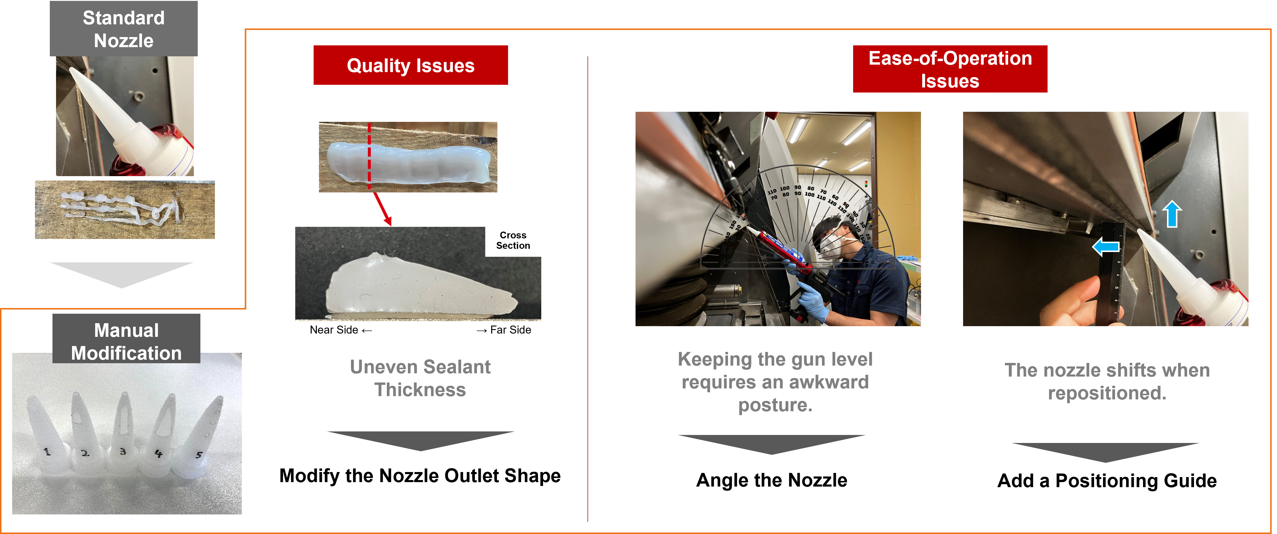
Figure 1. Quality and ease-of-operations issues identified through a quick trial using manually modified nozzles.
Quality Challenges
Cutting a wider slot into the nozzle allowed the sealant to be applied over a greater width. However, an examination of the sealant’s cross section showed that its thickness varied between the near and far sides. The outlet geometry therefore needed to be redesigned to produce a uniform layer.
Ease-of-Operation Challenges
Applying sealant to the chamber ceiling was particularly difficult because operators had to keep the dispensing gun horizontal, placing a physical burden on them. The nozzle also tended to shift as it moved along the application area, contributing to inconsistent results.
Based on these findings, we defined three design measures:
- Modify the nozzle outlet geometry.
- Angle the nozzle.
- Add a positioning guide.
Optimizing the Outlet Geometry Using CFD Analysis
Because repeated physical prototyping would have taken considerable time, we used CFD analysis to optimize the outlet geometry.
The first step was to determine how to represent the observed application result in the simulation. Uneven sealant thickness indicates that more material is discharged where the layer is thicker and less where it is thinner. Because local flow-rate trends can be evaluated from the velocity distribution, we compared the simulated distribution with the actual application result.
A model of the rectangular outlet used in the manually modified nozzle reproduced the same tendency observed in practice: flow velocity was higher on the near side. This confirmed that the analysis could be used to evaluate outlet geometries before physical prototyping. We then sought a design that would produce a more uniform velocity distribution.
we conducted a parametric study by varying the outlet dimensions at the tip and base. The study included a 4 mm tip-side dimension combined with base-side dimensions ranging from 1 to 3 mm.
The comparison showed that a 4 mm tip-side dimension and a 2 mm base-side dimension produced the most uniform velocity across the outlet. Testing a nozzle with this geometry confirmed that it reduced the difference in sealant thickness between the near and far sides.
To improve ease of operation, the design also incorporated a bent section that angled the nozzle tip and a positioning guide that prevented lateral movement. Together, these features improved the operator’s working posture and helped maintain a stable application position.
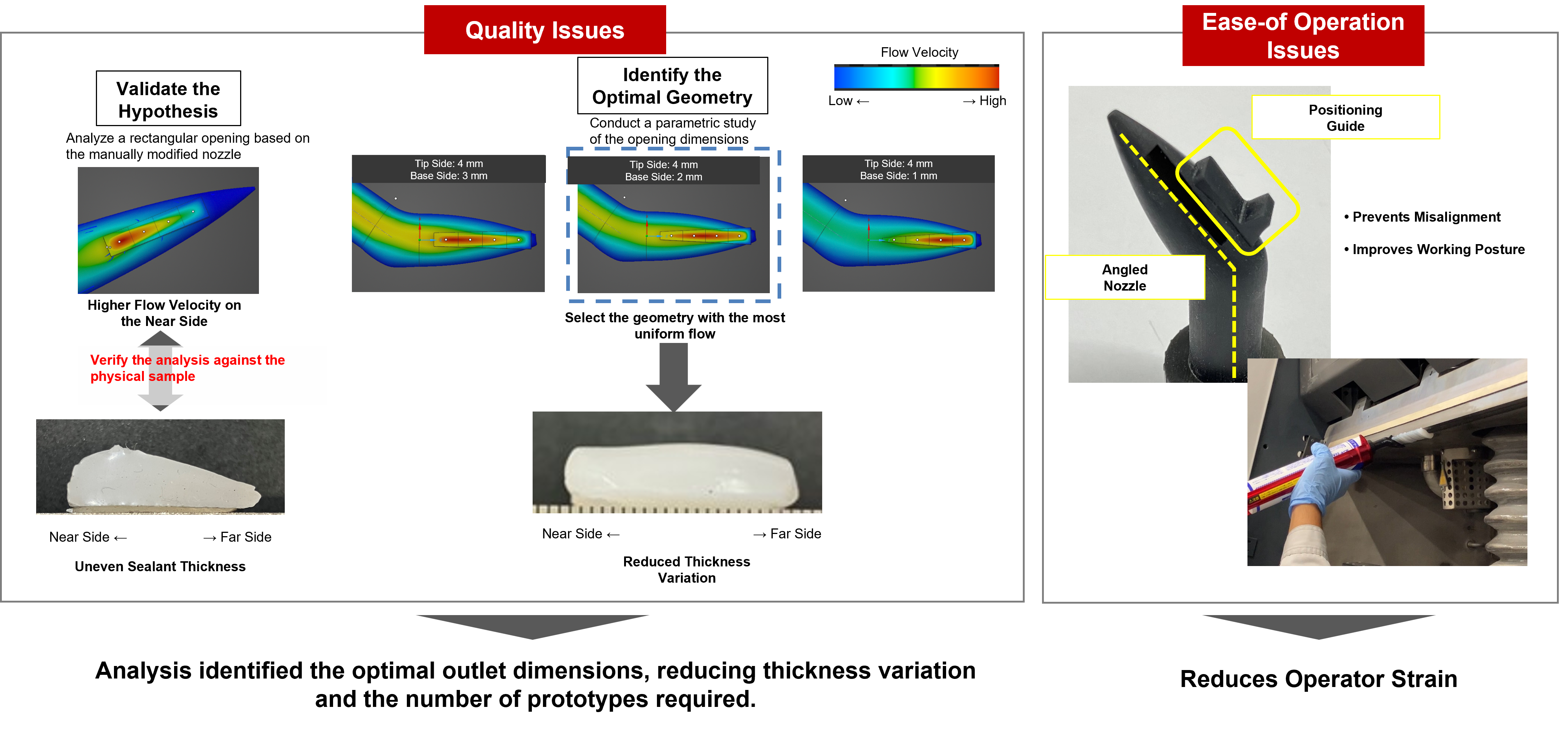
Figure 2. Parametric study of the outlet geometry using CFD analysis, along with the addition of an angled structure and positioning feature.
3D-Printed Nozzle Production and Implementation Results
The optimized design identified through CFD analysis was produced using a 3D printer. Additive manufacturing made it possible to integrate the complex outlet geometry, bent section, and positioning guide into a single component. The nozzle could also be prototyped and produced quickly without a mold.
Implementation of the new nozzle delivered three results:
- Sealant could be applied at a consistent width and thickness.
- Variation in the finished result between operators was reduced.
- Time per application was reduced from approximately 30 minutes to 3 minutes—a 90% reduction in labor time.
By using analysis to narrow down the optimal outlet dimensions before fabrication, we achieved the required quality improvement while minimizing the number of physical prototypes.
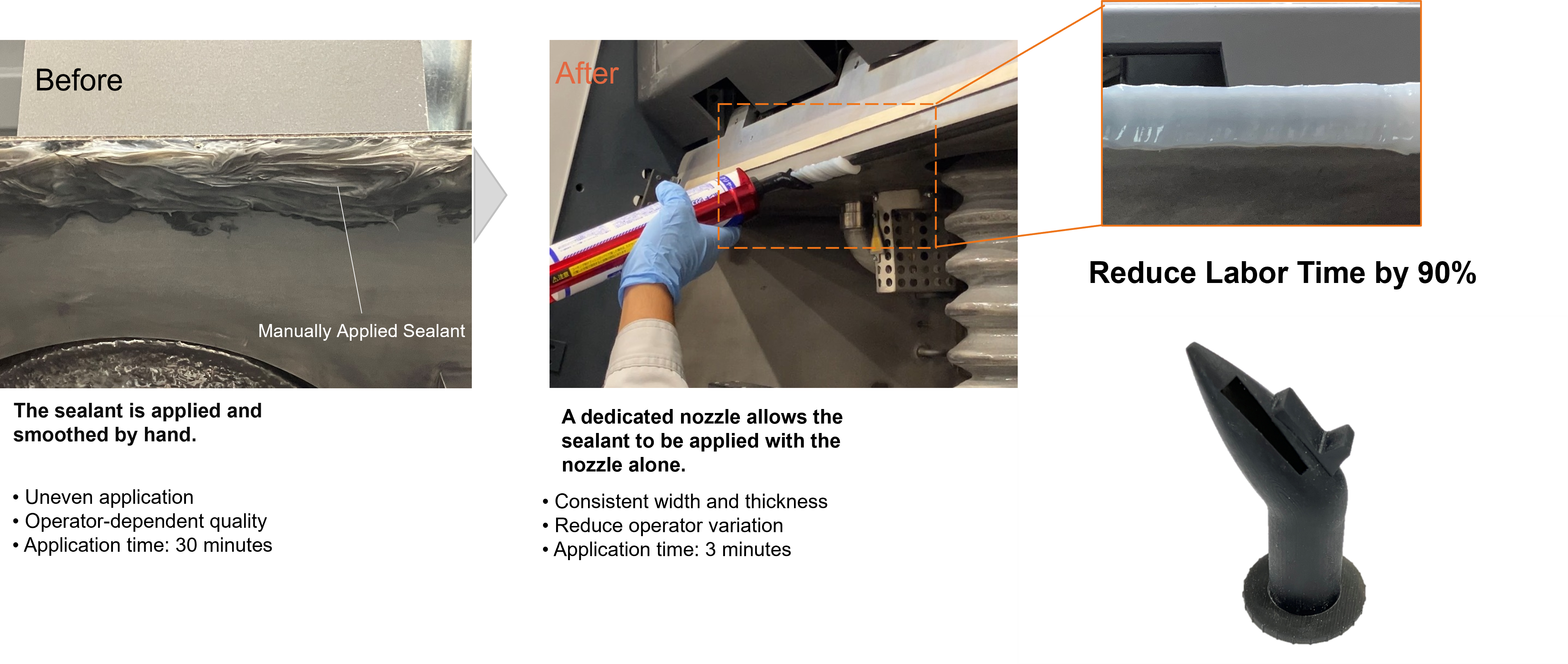
Figure 3. Before-and-after comparison following the introduction of the new nozzle, resulting in a 90% reduction in labor time.
Future Outlook
This case demonstrates that combining 3D printing with simulation can enable data-driven design improvements even for small jigs and tools used on the production floor.
Small-scale improvements to nozzles and jigs are relatively accessible starting points for production-engineering initiatives. The same approach could also be applied to other dispensing and discharge tools and related equipment components.
Going forward, SOLIZE PARTNERS will continue to build on the knowledge gained through our internal applications and use those insights to address a wide range of production-floor challenges.
Closing Message
SOLIZE PARTNERS combines design, simulation, and 3D-printing technologies to help address challenges at customers’ production sites.
In addition to supporting the introduction and effective use of 3D printers, the company applies simulation technologies, including CFD analysis, to enable efficient, data-driven design improvements for small components such as jigs and nozzles.
Please contact SOLIZE PARTNERS regarding equipment improvements or opportunities to improve operational efficiency in production engineering.
Contact: marketing.spt@solize.com

© 2026 SOLIZE Corporation All Rights Reserved.